New magnetic coupling pad with circular geometry for wireless power transfer applications
Main Article Content
Article Sidebar

Abstract
Abstract
With features like convenience, fully automatable and safety, Wireless Power Transfer(WPT) technology have the ability revolutionize the EV charging infrastructure[1, 2]. The difference between plug-in charging and wireless charging is a magnetic coupler, which transfers power without using cables. The basic structure of WPT shown in the fig. 1. The performance of the WPT operation mainly depends on the coil design, core and shielding. Researchers introduced different types of magnetic coupler designs for enhancing magnetic power transfer capabilities [3].
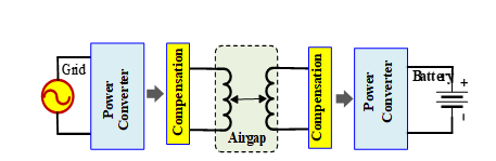
Fig.1. Basic structure of inductive wireless charging system.
In particular multi coil structures like DD, DDQ Bi polar pad, quadruple pad and many more proposed as a solution to challenges like low coupling factor, low mutual inductance and misalignment. Furthermore, these multi coil pads shown the tolerance towards movement of vehicles that is more useful in dynamic wireless charging systems (charging of EV while moving). Among the all the pads circular pads have same misalignment tolerance in all directions and they have simple construction and easy to operate. Due to their non-directional behaviour, EV can approach towards charging point from different directions which provides flexibility for driver. These all features suitable for Static Wireless Charging (SWC) applications (charging of EV in stationary position). Therefore, despite having low mutual inductance and coupling factor compared to similar sized pads with identical air gap, circular pads are still mostly used geometric structure for SWC applications[4] [5].
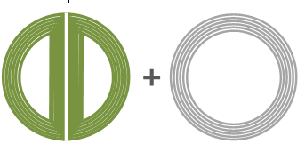
Fig.2. Proposed coil model.
Considering the features of circular geometry. In this article, a new pad proposed to enhance the power transfer capabilities of circular shaped magnetic pad. Proposed model consist of multiple coils to gain more mutual inductance and misalignment tolerance operation. The proposed pad shown in fig. 2, which consisting of two coils one is circular shaped DD coil and another one circular coil acts as a quadrature coil.
Initial analysis of proposed pad done in Ansys Maxwell 3D FEA simulation software with different approaches and compared with conventional circular pad. Approach-1: proposed pad as transmitting coil and circular pad as a receiving coil.Approach-2 proposed pad(position of quadrature coil changed) as a transmitting coil and circular coil in receiver side.Approach-3 is proposed model as transmitter and Factors considered for the analysis are mutual inductance and similar air gap (50 mm) and simulation is done without using ferrites. Model diagrams of different approaches shown in fig. 3. Table 1 presents sel af and mutual inductances of different approaches in that proposed pad utilized as a transmitter with different receiving coils and they are compared with circular model (transmitter and receiver both are circular coils. Fig .4 shows the magnetic flux path in circular model in FEA simulation.
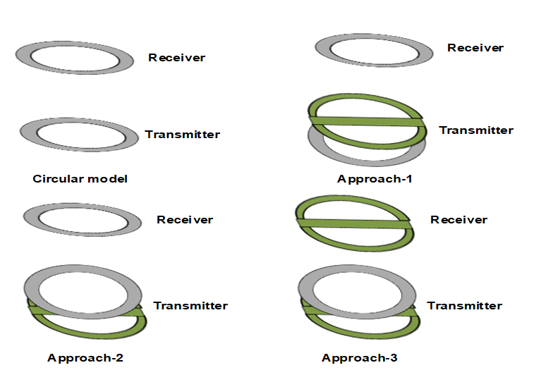
Fig.3. Different approaches followed in simulation.
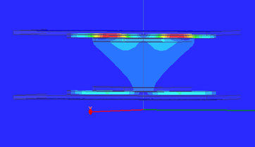
Fig.4. Magnetic flux path in FEA simulation.
Table 1. Comparison of different approaches
50mm air gap
Circular model
Approach-1
Approach-2
Approach-3
Mutual Inductance
327nH
303nH
357nH
127nH
Self-inductance of primary
4.4µH
8.7µH
9µH
8.7µH
Self-inductance of Secondary
4.4µH
4.53µH
4.53µH
4.50µH
By observing table 1, the approach 2 offers better performance than the conventional circular model in terms of mutual inductance. This method is useful in static charging applications to improve the charging time and power transfer capability. Adding of compensation and ferrites improves the mutual inductance and coupling factor.
How to Cite
Article Details
Magnetic Pad, Static Wireless Power Transfer, Circular Geometry, FEA, WPT
https://doi.org/10.1109/tte.2017.2780627
[2] M. Kesler, "Highly resonant wireless power transfer: safe, efficient, and over distance," Witricity corporation, 1-32, 2013.
https://witricity.com/wp-content/uploads/2016/12/White_Paper_20161218.pdf
[3] A. A. Mohamed, A. A. Shaier et al. Applied Energy, 262, 114584, 2020.
https://doi.org/10.1016/j.apenergy.2020.114584
[4] T. Campi, S. Cruciani, IEEE Transactions on Electromagnetic Compatibility, 62, 1398-1405, 2020.
https://doi.org/10.1109/temc.2020.2988463
[5] K. Aditya, Electrical Engineering, 100, 1819-1826, 2018.
https://doi.org/10.1007/s00202-017-0663-7.